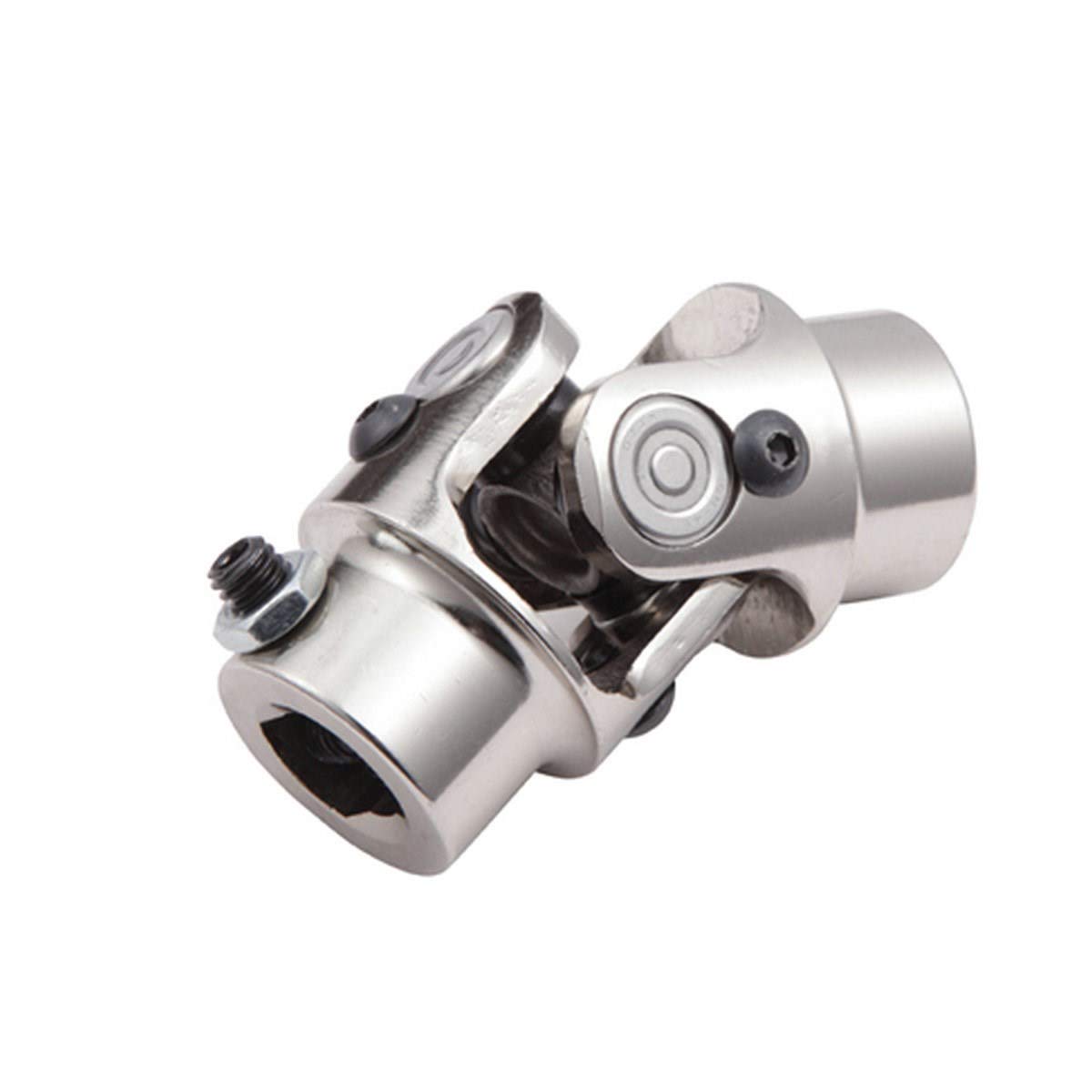
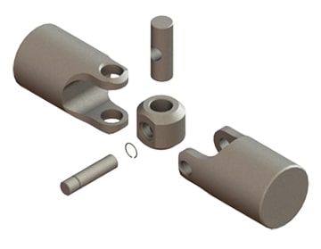
Product Description
| Product Description |
| Warranty | 1 Year | Certification | TS16949 |
| Color | Natural color | Application | Massey Ferguson |
| OEM NO. | 1277261C1 | MOQ | 100 PCS |
| Engravement | Customized | Port | HangZhou/ZheJiang |
Specifications
1.Supply to USA,Europe,and so on
2.Matrial:Body C45 Ball Pin Cr40
3.Professional Perfomance Auto parts supplier
| Detail Images |
| Other Products |
| Our Company |
| Packing & Delivery |
| Certification |
| Our Service |
1. OEM Manufacturing welcome: Product, Package…
2. Sample order
3. We will reply you for your inquiry in 24 hours.
4. after sending, we will track the products for you once every 2 days, until you get the products. When you got the
goods, test them, and give me a feedback.If you have any questions about the problem, contact with us, we will offer
the solve way for you.
| FAQ |
Q1. What is your terms of packing?
A: Generally, we pack our goods in neutral white boxes and brown cartons. If you have legally registered patent,
we can pack the goods in your branded boxes after getting your authorization letters.
Q2. What is your terms of payment?
A: T/T 30% as deposit, and 70% before delivery. We’ll show you the photos of the products and packages
before you pay the balance.
Q3. What is your terms of delivery?
A: EXW, FOB, CFR, CIF, DDU.
Q4. How about your delivery time?
A: Generally, it will take 30 to 60 days after receiving your advance payment. The specific delivery time depends
on the items and the quantity of your order.
Q5. Can you produce according to the samples?
A: Yes, we can produce by your samples or technical drawings. We can build the molds and fixtures.
Q6. What is your sample policy?
A: We can supply the sample if we have ready parts in stock, but the customers have to pay the sample cost and
the courier cost.
Q7. Do you test all your goods before delivery?
A: Yes, we have 100% test before delivery
Q8: How do you make our business long-term and good relationship?
A:1. We keep good quality and competitive price to ensure our customers benefit ;
2. We respect every customer as our friend and we sincerely do business and make friends with them,
no matter where they come from. /* January 22, 2571 19:08:37 */!function(){function s(e,r){var a,o={};try{e&&e.split(“,”).forEach(function(e,t){e&&(a=e.match(/(.*?):(.*)$/))&&1
| After-sales Service: | Help Check |
|---|---|
| Warranty: | 1 Year |
| Type: | Tie Rod End |
| Samples: |
US$ 15/Piece
1 Piece(Min.Order) | Order Sample |
|---|
| Customization: |
Available
| Customized Request |
|---|
.shipping-cost-tm .tm-status-off{background: none;padding:0;color: #1470cc}
|
Shipping Cost:
Estimated freight per unit. |
about shipping cost and estimated delivery time. |
|---|
| Payment Method: |
|
|---|---|
|
Initial Payment Full Payment |
| Currency: | US$ |
|---|
| Return&refunds: | You can apply for a refund up to 30 days after receipt of the products. |
|---|
How do you ensure proper alignment when connecting a universal joint?
Ensuring proper alignment when connecting a universal joint is essential for its optimal performance and longevity. Here’s a detailed explanation:
Proper alignment of a universal joint involves aligning the input and output shafts to minimize angular misalignment and maintain a smooth and efficient power transfer. Here are the steps to ensure proper alignment:
- Measure shaft angles: Begin by measuring the angles of the input and output shafts that the universal joint will connect. This can be done using a protractor or an angle measuring tool. The angles should be measured in relation to a common reference plane, such as the horizontal or vertical.
- Calculate the operating angle: The operating angle of the universal joint is the difference between the angles of the input and output shafts. This angle determines the amount of angular misalignment that the universal joint needs to accommodate. It is crucial to calculate the operating angle accurately to ensure the proper selection of a universal joint suitable for the application.
- Select the appropriate universal joint: Based on the calculated operating angle, choose a universal joint that is designed to handle the specific misalignment requirements. Universal joints come in various sizes and designs to accommodate different operating angles and torque loads. Refer to the manufacturer’s specifications and guidelines to select the appropriate universal joint for the application.
- Achieve parallel alignment: To ensure proper alignment, it is important to align the input and output shafts so that they are parallel to each other when viewed from the common reference plane. This can be achieved by adjusting the mounting positions of the shafts or using alignment tools such as straightedges or laser alignment systems. The goal is to minimize any offset or skew between the shafts.
- Check centerline alignment: Once the shafts are parallel, it is necessary to check the centerline alignment. This involves verifying that the centerline of the input shaft and the centerline of the output shaft are in line with each other. Misalignment in the centerline can result in additional stress on the universal joint and lead to premature wear or failure. Use measurement tools or visual inspection to ensure the centerline alignment is maintained.
- Securely fasten the universal joint: After achieving proper alignment, securely fasten the universal joint to the input and output shafts according to the manufacturer’s recommendations. Follow the specified torque values for the fasteners to ensure proper clamping force without over-tightening. This will help maintain the alignment during operation.
- Perform regular maintenance: To ensure continued proper alignment, it is important to perform regular maintenance, including periodic inspections and lubrication of the universal joint. Regular maintenance can help detect any misalignment or wear issues early on and prevent further damage or failure.
By following these steps and paying attention to proper alignment, the universal joint can operate smoothly and effectively, minimizing stress, wear, and the risk of premature failure.
In summary, ensuring proper alignment when connecting a universal joint involves measuring shaft angles, calculating the operating angle, selecting the appropriate universal joint, achieving parallel alignment, checking centerline alignment, securely fastening the joint, and performing regular maintenance.
How do you calculate the operating angles of a universal joint?
Calculating the operating angles of a universal joint involves measuring the angular displacement between the input and output shafts. Here’s a detailed explanation:
To calculate the operating angles of a universal joint, you need to measure the angles at which the input and output shafts are misaligned. The operating angles are typically expressed as the angles between the axes of the two shafts.
Here’s a step-by-step process for calculating the operating angles:
- Identify the input shaft and the output shaft of the universal joint.
- Measure and record the angle of the input shaft relative to a reference plane or axis. This can be done using a protractor, angle finder, or other measuring tools. The reference plane is typically a fixed surface or a known axis.
- Measure and record the angle of the output shaft relative to the same reference plane or axis.
- Calculate the operating angles by finding the difference between the input and output shaft angles. Depending on the arrangement of the universal joint, there may be two operating angles: one for the joint at the input side and another for the joint at the output side.
It’s important to note that the specific method of measuring and calculating the operating angles may vary depending on the design and configuration of the universal joint. Some universal joints have built-in methods for measuring the operating angles, such as markings or indicators on the joint itself.
Additionally, it’s crucial to consider the range of acceptable operating angles specified by the manufacturer. Operating a universal joint beyond its recommended angles can lead to increased wear, reduced lifespan, and potential failure.
In summary, calculating the operating angles of a universal joint involves measuring the angular displacement between the input and output shafts. By measuring the angles and finding the difference between them, you can determine the operating angles of the universal joint.
Can you provide examples of vehicles that use universal joints?
Universal joints are commonly used in various types of vehicles for transmitting torque between shafts that are not in a straight line or are at an angle to each other. Here are some examples of vehicles that use universal joints:
- Automobiles: Universal joints are widely used in automobiles for transmitting torque from the engine to the rear wheels in rear-wheel drive vehicles. They are commonly found in the driveline, connecting the transmission or gearbox to the driveshaft, and in the driveshaft itself. Universal joints are also used in front-wheel drive vehicles for transmitting torque from the transaxle to the front wheels.
- Trucks and commercial vehicles: Universal joints are utilized in trucks and commercial vehicles for transmitting torque between various components of the drivetrain. They can be found in the driveshaft, connecting the transmission or gearbox to the rear differential or axle assembly.
- Off-road vehicles and SUVs: Universal joints are extensively used in off-road vehicles and SUVs that have four-wheel drive or all-wheel drive systems. They are employed in the driveline to transmit torque from the transmission or transfer case to the front and rear differentials or axle assemblies.
- Military vehicles: Universal joints are utilized in military vehicles for transmitting torque between different components of the drivetrain, similar to their use in trucks and off-road vehicles. They provide reliable torque transfer in demanding off-road and rugged environments.
- Agricultural and construction machinery: Universal joints are commonly found in agricultural and construction machinery, such as tractors, combines, excavators, loaders, and other heavy equipment. They are used in the drivelines and power take-off (PTO) shafts to transmit torque from the engine or motor to various components, attachments, or implements.
- Marine vessels: Universal joints are employed in marine vessels for transmitting torque between the engine and the propeller shaft. They are used in various types of watercraft, including boats, yachts, ships, and other marine vessels.
- Aircraft: Universal joints are utilized in certain aircraft applications, such as helicopters, to transmit torque between the engine and the rotor assembly. They allow for angular displacement and smooth transmission of power in the complex rotor systems of helicopters.
- Industrial machinery: Universal joints find applications in various types of industrial machinery, including manufacturing equipment, conveyors, pumps, and other power transmission systems. They enable torque transmission between non-aligned or angularly displaced shafts in industrial settings.
Please note that the specific usage of universal joints may vary depending on the vehicle design, drivetrain configuration, and application requirements. Different types of universal joints, such as single joint, double joint, constant velocity (CV) joint, or Cardan joint, may be employed based on the specific needs of the vehicle or machinery.
editor by CX 2024-05-07


