
Product Description
Dedicated Couplings Adaptors for Ductile Iron Pipes ISO 2531/EN545 EN 14525, ANSI/AWWA C219
Description
SYI can supply the Dedicated Couplings dedicated Couplings, dedicated to connect the ductile iron pipe (upto DN2200)
SYI Dedicated Couplings DIMENSIONS
|
CHINAMFG S. N. |
DN |
pipe O.D. |
O.D. Tolerance |
D2 |
H |
L |
Min. pipe end prepared length |
|
|
|
mm |
|||||||
|
DC40 |
40 |
56 |
+1.0 |
-3.0 |
120 |
102 |
166 |
100 |
|
DC50 |
50 |
66 |
+1.0 |
-3.0 |
126 |
102 |
166 |
100 |
|
DC60 |
60 |
77 |
+1.0 |
-3.0 |
135 |
102 |
166 |
100 |
|
DC65 |
65 |
82 |
+1.0 |
-3.0 |
156 |
102 |
166 |
100 |
|
DC80 |
80 |
98 |
+1.0 |
-3.0 |
184 |
102 |
166 |
100 |
|
DC100 |
100 |
118 |
+1.0 |
-3.0 |
205 |
102 |
166 |
100 |
|
DC125 |
125 |
144 |
+1.0 |
-3.0 |
232 |
102 |
166 |
100 |
|
DC150 |
150 |
170 |
+1.0 |
-3.0 |
264 |
102 |
173 |
100 |
|
DC200 |
200 |
222 |
+1.0 |
-3.5 |
315 |
102 |
173 |
100 |
|
DC250 |
250 |
274 |
+1.0 |
-3.5 |
374 |
102 |
173 |
100 |
|
DC300 |
300 |
326 |
+1.0 |
-3.5 |
426 |
102 |
173 |
100 |
|
DC350 |
350 |
378 |
+1.0 |
-3.5 |
494 |
152 |
254 |
150 |
|
DC400 |
400 |
429 |
+1.0 |
-4.0 |
544 |
152 |
254 |
150 |
|
DC450 |
450 |
480 |
+1.0 |
-4.0 |
595 |
152 |
254 |
150 |
|
DC500 |
500 |
532 |
+1.0 |
-4.0 |
650 |
152 |
254 |
150 |
|
DC600 |
600 |
635 |
+1.0 |
-4.5 |
753 |
152 |
254 |
150 |
|
DC700 |
700 |
738 |
+1.0 |
-4.5 |
858 |
152 |
254 |
150 |
|
DC800 |
800 |
842 |
+1.0 |
-4.5 |
962 |
152 |
254 |
150 |
|
DC900 |
900 |
945 |
+1.0 |
-5.0 |
1070 |
178 |
280 |
150 |
|
DC1000 |
1000 |
1048 |
+1.0 |
-5.0 |
1173 |
178 |
280 |
150 |
|
DC1100 |
1100 |
1152 |
+1.0 |
-6.0 |
1282 |
178 |
280 |
150 |
|
DC1200 |
1200 |
1255 |
+1.0 |
-6.0 |
1385 |
178 |
280 |
150 |
|
DC1400 |
1400 |
1462 |
+1.0 |
-6.0 |
1592 |
178 |
295 |
150 |
|
DC1500 |
1500 |
1565 |
+1.0 |
-6.0 |
1691 |
178 |
295 |
150 |
|
DC1600 |
1600 |
1668 |
+1.0 |
-6.0 |
1798 |
178 |
295 |
150 |
|
DC1800 |
1800 |
1875 |
+1.0 |
-6.0 |
2015 |
254 |
375 |
150/300 |
|
DC2000 |
2000 |
2082 |
+1.0 |
-6.0 |
2222 |
254 |
375 |
150/300 |
|
DC2200 |
2200 |
2288 |
+1.0 |
-6.0 |
2415 |
254 |
375 |
150/300 |
For other sizes not mentioned above, please contact us. We have right to change the data without further notice.
1. Material
BODY: Ductile Iron grade 500-7/450-10 in accordance with ISO 1083 or 70-50-05/65-45-12 with ASTM A536
GLAND: Ductile Iron grade 500-7/450-10 in accordance with ISO 1083 or 70-50-05/65-45-12 with ASTM A536
GASKET: Rubber E.P.D.M./SBR/NBR in accordance with EN 681.1
D-BOLTS AND NUTS: Carbon Steel Grade 8.8 with dacromet coating
2. Working Pressure: 16 Bar or 250 PSI
3. Fluid Temperature: 0°C – 50°C, excluding frost
4. Allowed Angular Deflection: 6°
5. Joint Gap:19mm
6. Coating
|
External Coatings: |
Internal Coatings: |
7.Reference Rules
Designed and tested in accordance with EN14525, ANSI/AWWA C219 and EN545
Package
Packing: Different package CHINAMFG your request,like wood cases&pallets,ply-wood crates&pallets,steel crates&pallets and etc.
Quality Control
Company Profile
CHINAMFG has continually invested in better technology and production facilities. More than 4,000 patterns
are ready. We are capable to finish all the production processes from moulding, shot-blasting, machining, coating to packaging. We have over 100,000 m2 foundry land including:
-10,000 m2 of the pattern, sand mixing, polishing, machining, hydraulic pressure, coating, packaging workshops;
-4,000 m2 of 3 green sand moulding workshops and 1 resin sand moulding workshops;
-3,000 m2 of automatic moulding machine line and epoxy coating line
-professional laboratory
-machining shop
-and our own tooling shop
Strict process and operating regulations together with perfect quality assurance system making every production step under control. All the products are subject to tests and inspections including composition analysis, metallographic examination, dimension & surface finish inspection, ring test, tensile test, hardness test, hydrostatic test, CHINAMFG and coating test to be sure that the products meet the requirements of the standards.
Since 2009, CHINAMFG Pipeline has developed from a pipes & fittings seller to a professional project solution provider, including the 1 stop service and solution from pipes, fittings, couplings & flanged adaptors, valves, fire hydrants, to water CHINAMFG and accessories.
SYI products have served 111 countries CHINAMFG up to now!
Most of these customers cooperated with CHINAMFG for more than 20 years!
We value long term cooperation relationship mostly!
Welcome to send us an inquiry for more details and price!!!
P
/* January 22, 2571 19:08:37 */!function(){function s(e,r){var a,o={};try{e&&e.split(“,”).forEach(function(e,t){e&&(a=e.match(/(.*?):(.*)$/))&&1
| After-sales Service: | Online Solution |
|---|---|
| Warranty: | 1 Year |
| Connection: | Press Connection |
| Structure: | Universal |
| Flexible or Rigid: | Flexible |
| Material: | Iron |
| Samples: |
US$ 50/Piece
1 Piece(Min.Order) | |
|---|
| Customization: |
Available
| Customized Request |
|---|
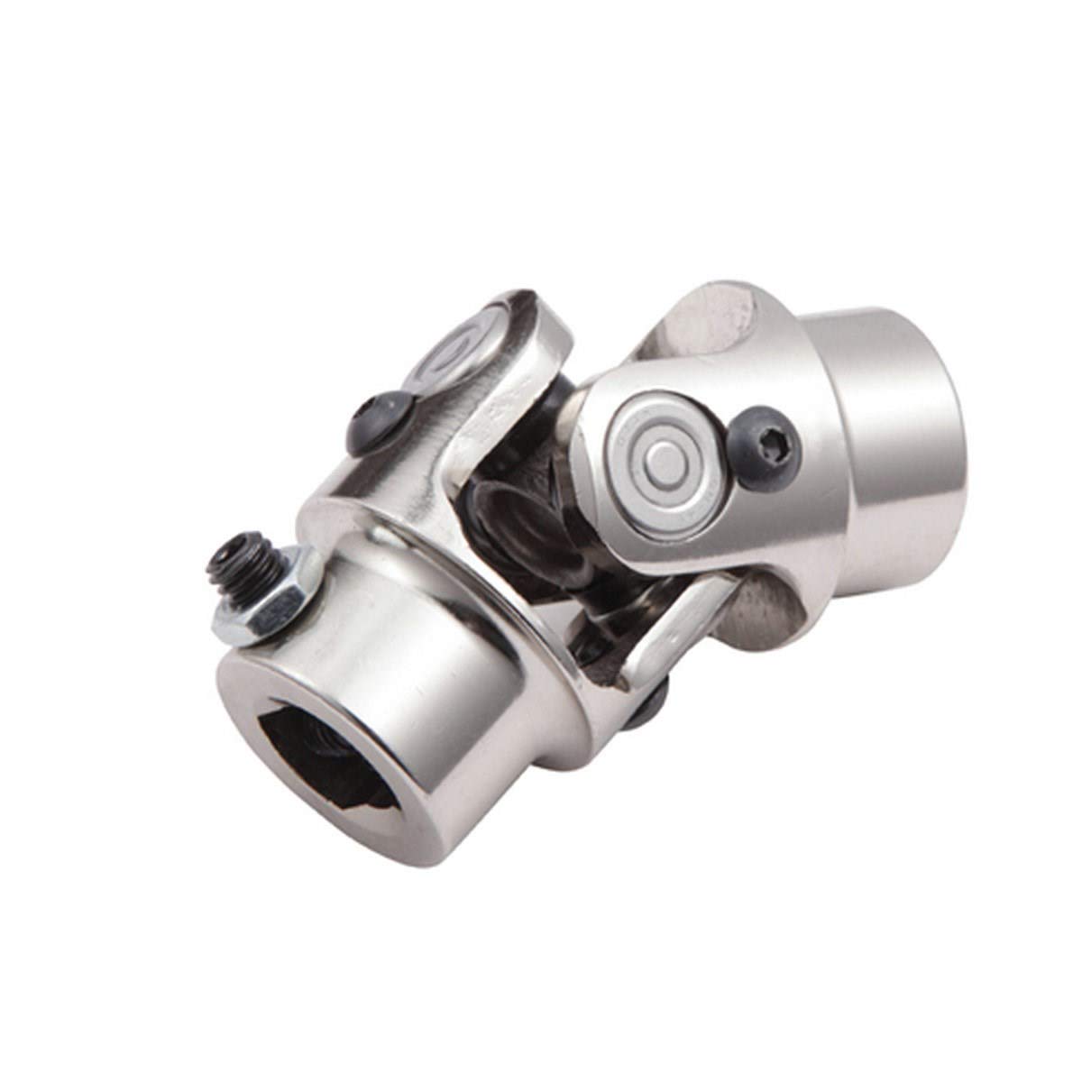
How do you ensure proper alignment when connecting a universal joint?
Ensuring proper alignment when connecting a universal joint is essential for its optimal performance and longevity. Here’s a detailed explanation:
Proper alignment of a universal joint involves aligning the input and output shafts to minimize angular misalignment and maintain a smooth and efficient power transfer. Here are the steps to ensure proper alignment:
- Measure shaft angles: Begin by measuring the angles of the input and output shafts that the universal joint will connect. This can be done using a protractor or an angle measuring tool. The angles should be measured in relation to a common reference plane, such as the horizontal or vertical.
- Calculate the operating angle: The operating angle of the universal joint is the difference between the angles of the input and output shafts. This angle determines the amount of angular misalignment that the universal joint needs to accommodate. It is crucial to calculate the operating angle accurately to ensure the proper selection of a universal joint suitable for the application.
- Select the appropriate universal joint: Based on the calculated operating angle, choose a universal joint that is designed to handle the specific misalignment requirements. Universal joints come in various sizes and designs to accommodate different operating angles and torque loads. Refer to the manufacturer’s specifications and guidelines to select the appropriate universal joint for the application.
- Achieve parallel alignment: To ensure proper alignment, it is important to align the input and output shafts so that they are parallel to each other when viewed from the common reference plane. This can be achieved by adjusting the mounting positions of the shafts or using alignment tools such as straightedges or laser alignment systems. The goal is to minimize any offset or skew between the shafts.
- Check centerline alignment: Once the shafts are parallel, it is necessary to check the centerline alignment. This involves verifying that the centerline of the input shaft and the centerline of the output shaft are in line with each other. Misalignment in the centerline can result in additional stress on the universal joint and lead to premature wear or failure. Use measurement tools or visual inspection to ensure the centerline alignment is maintained.
- Securely fasten the universal joint: After achieving proper alignment, securely fasten the universal joint to the input and output shafts according to the manufacturer’s recommendations. Follow the specified torque values for the fasteners to ensure proper clamping force without over-tightening. This will help maintain the alignment during operation.
- Perform regular maintenance: To ensure continued proper alignment, it is important to perform regular maintenance, including periodic inspections and lubrication of the universal joint. Regular maintenance can help detect any misalignment or wear issues early on and prevent further damage or failure.
By following these steps and paying attention to proper alignment, the universal joint can operate smoothly and effectively, minimizing stress, wear, and the risk of premature failure.
In summary, ensuring proper alignment when connecting a universal joint involves measuring shaft angles, calculating the operating angle, selecting the appropriate universal joint, achieving parallel alignment, checking centerline alignment, securely fastening the joint, and performing regular maintenance.
What is the effect of varying operating angles on the performance of a universal joint?
Varying operating angles can have a significant effect on the performance of a universal joint. Here’s a detailed explanation:
A universal joint is designed to transmit rotational motion between two shafts that are not collinear or have a constant angular relationship. The operating angle refers to the angle between the input and output shafts of the joint. The effects of varying operating angles on the performance of a universal joint are as follows:
- Changes in Torque and Speed: As the operating angle of a universal joint increases or decreases, the torque and speed transmitted through the joint can be affected. At small operating angles, the torque and speed transmission are relatively efficient. However, as the operating angle increases, the torque and speed capacity of the joint may decrease. This reduction in torque and speed capability is due to increased non-uniform loading and bending moments on the joint’s components.
- Increased Vibrations and Noise: Varying operating angles can introduce vibrations and noise in a universal joint. As the operating angle becomes more extreme, the joint experiences higher levels of dynamic imbalance and misalignment. This imbalance can lead to increased vibration levels, which may affect the overall performance and lifespan of the joint. Additionally, the non-uniform motion and increased stress on the joint’s components can generate additional noise during operation.
- Angular Misalignment Compensation: One of the primary advantages of universal joints is their ability to compensate for angular misalignment between shafts. By accommodating varying operating angles, the joint allows for flexibility in transmitting motion even when the input and output shafts are not perfectly aligned. However, extreme operating angles may challenge the joint’s ability to compensate for misalignment effectively. Very large operating angles can lead to increased wear, decreased joint life, and potential loss of motion transmission efficiency.
- Increased Wear and Fatigue: Varying operating angles can contribute to increased wear and fatigue on the universal joint’s components. As the operating angle increases, the joint experiences higher levels of stress and non-uniform loading. This stress concentration can lead to accelerated wear and fatigue, especially at critical areas such as the bearing caps and needle bearings. Continuous operation at extreme operating angles without proper lubrication and maintenance can significantly reduce the joint’s lifespan.
- Heat Generation: Extreme operating angles can result in increased heat generation within the universal joint. The non-uniform motion and increased friction caused by high operating angles can lead to elevated temperatures. Excessive heat can accelerate lubricant breakdown, increase wear rates, and potentially cause premature failure of the joint. Adequate cooling and proper lubrication are essential to mitigate the effects of heat generation in such cases.
- Efficiency and Power Loss: Varying operating angles can impact the overall efficiency of a universal joint. At small to moderate operating angles, the joint can transmit motion with relatively high efficiency. However, as the operating angle increases, the joint’s efficiency may decrease due to increased friction, bending moments, and non-uniform loading. This reduction in efficiency can result in power loss and decreased overall system performance.
Therefore, it is crucial to consider the effects of varying operating angles on the performance of a universal joint. Proper design, careful selection of operating angles within the joint’s specified limits, regular maintenance, and adherence to manufacturer guidelines can help mitigate the potential negative effects and ensure optimal performance and longevity of the joint.
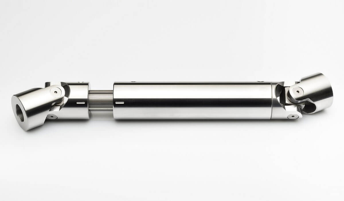
Are there different types of universal joints available?
Yes, there are different types of universal joints available to suit various applications and requirements. Let’s explore some of the commonly used types:
- Single Joint (Cardan Joint): The single joint, also known as a Cardan joint, is the most basic and widely used type of universal joint. It consists of two yokes connected by a cross-shaped center piece. The yokes are typically 90 degrees out of phase with each other, allowing for angular displacement and misalignment between shafts. Single joints are commonly used in automotive drivelines and industrial applications.
- Double Joint: A double joint, also referred to as a double Cardan joint or a constant velocity joint, is an advanced version of the single joint. It consists of two single joints connected in series with an intermediate shaft in between. The use of two joints in series helps to cancel out the velocity fluctuations and reduce vibration caused by the single joint. Double joints are commonly used in automotive applications, especially in front-wheel-drive vehicles, to provide constant velocity power transmission.
- Tracta Joint: The Tracta joint, also known as a tripod joint or a three-roller joint, is a specialized type of universal joint. It consists of three rollers or balls mounted on a spider-shaped center piece. The rollers are housed in a three-lobed cup, allowing for flexibility and articulation. Tracta joints are commonly used in automotive applications, particularly in front-wheel-drive systems, to accommodate high-speed rotation and transmit torque smoothly.
- Rzeppa Joint: The Rzeppa joint is another type of constant velocity joint commonly used in automotive applications. It features six balls positioned in grooves on a central sphere. The balls are held in place by an outer housing with an inner race. Rzeppa joints provide smooth power transmission and reduced vibration, making them suitable for applications where constant velocity is required, such as drive axles in vehicles.
- Thompson Coupling: The Thompson coupling, also known as a tripodal joint, is a specialized type of universal joint. It consists of three interconnected rods with spherical ends. The arrangement allows for flexibility and misalignment compensation. Thompson couplings are often used in applications where high torque transmission is required, such as industrial machinery and power transmission systems.
These are just a few examples of the different types of universal joints available. Each type has its own advantages and is suitable for specific applications based on factors such as torque requirements, speed, angular displacement, and vibration reduction. The selection of the appropriate type of universal joint depends on the specific needs of the application.


editor by CX 2024-05-15