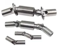
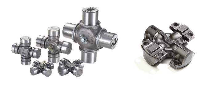
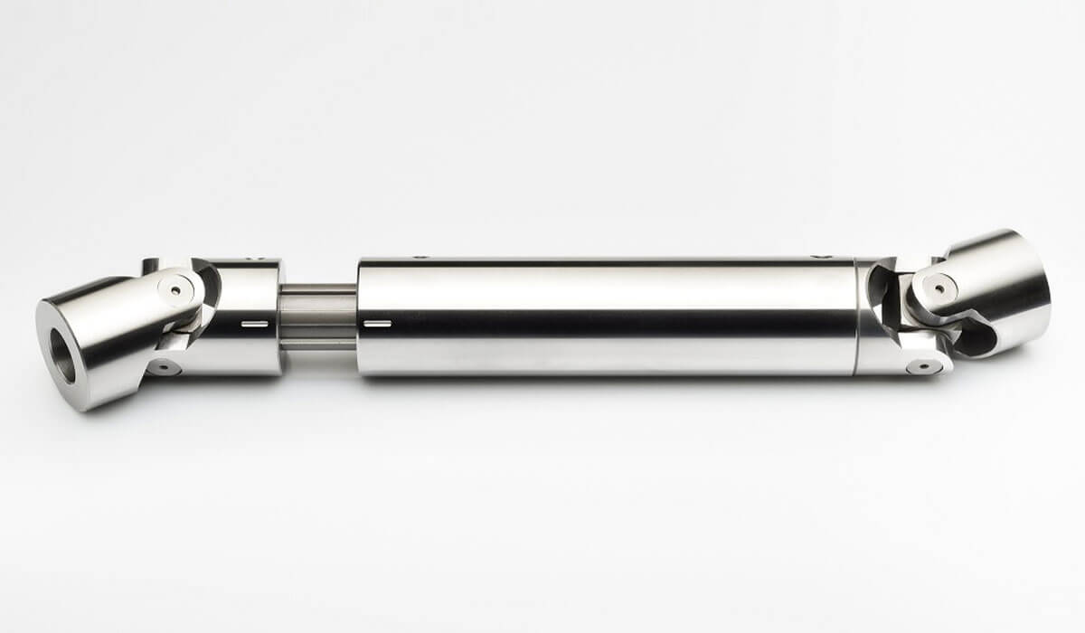
Product Description
| Spicer | P (mm) | R (mm) | Caterpillar | Precision | Rockwell | GKN | Alloy | Neapcon | Serie | Bearing type |
| 5-2002X | 33.34 | 79 | 644683 | 951 | CP2002 | HS520 | 1-2171 | 2C | 4LWT | |
| 5-2117X | 33.34 | 79 | 316117 | 994 | HS521 | 1-2186 | 2C | 4LWD | ||
| 5-2116X | 33.34 | 79 | 6S6902 | 952 | CP2116 | 1063 | 2C | 2LWT,2LWD | ||
| 5-3000X | 36.5 | 90.4 | 5D9153 | 536 | HS530 | 1711 | 3-3152 | 3C | 4LWT | |
| 5-3014X | 36.5 | 90.4 | 9K1976 | 535 | HS532 | 3C | 2LWT,2LWD | |||
| 5-4143X | 36.5 | 108 | 6K 0571 | 969 | HS545 | 1689 | 3-4143 | 4C | 4HWD | |
| 5-4002X | 36.5 | 108 | 6F7160 | 540 | CP4002 | HS540 | 1703 | 3-4138 | 4C | 4LWT |
| 5-4123X | 36.5 | 108 | 9K3969 | 541 | CP4101 | HS542 | 1704 | 3-4123 | 4C | 2LWT,2LWD |
| 5-4140X | 36.5 | 108 | 5M800 | 929 | CP4130 | HS543 | 3-4140 | 4C | 2LWT,2HWD | |
| 5-1405X | 36.5 | 108 | 549 | 1708 | 4C | 4LWD | ||||
| 5-4141X | 36.5 | 108 | 7M2695 | 996 | 4C | 2LWD,2HWD | ||||
| 5-5177X | 42.88 | 115.06 | 2K3631 | 968 | CP5177 | HS555 | 1728 | 4-5177 | 5C | 4HWD |
| 5-5000X | 42.88 | 115.06 | 7J5251 | 550 | CP5122 | HS550 | 1720 | 4-5122 | 5C | 4LWT |
| 5-5121X | 42.88 | 115.06 | 7J5245 | 552 | CP5101 | HS552 | 1721 | 4-5127 | 5C | 2LWT,2LWD |
| 5-5173X | 42.88 | 115.06 | 933 | HS553 | 1722 | 4-5173 | 5C | 2LWT,2HWD | ||
| 5-5000X | 42.88 | 115.06 | 999 | 5C | 4HWD | |||||
| 5-5139X | 42.88 | 115.06 | 5C | 2LWD,2HWD | ||||||
| 5-6102X | 42.88 | 140.46 | 643633 | 563 | CP62N-13 | HS563 | 1822 | 4-6114 | 6C | 2LWT,2HWD |
| 5-6000X | 42.88 | 140.46 | 641152 | 560 | CP62N-47 | HS560 | 1820 | 4-6143 | 6C | 4LWT |
| 5-6106X | 42.88 | 140.46 | 1S9670 | 905 | CP62N-49 | HS565 | 1826 | 4-6128 | 6C | 4HWD |
| G5-6103X | 42.88 | 140.46 | 564 | 1823 | 4-6103 | 6C | 2LWT,2LWD | |||
| G5-6104X | 42.88 | 140.46 | 566 | 1824 | 4-6104 | 6C | 4LWD | |||
| G5-6149X | 42.88 | 140.46 | 6C | 2LWD,2HWD | ||||||
| 5-7105X | 49.2 | 148.38 | 6H2577 | 927 | CP72N-31 | HS575 | 1840 | 5-7126 | 7C | 4HWD |
| 5-7000X | 49.2 | 148.32 | 8F7719 | 570 | CP72N-32 | HS570 | 1841 | 5-7205 | 7C | 4LWT |
| 5-7202X | 49.2 | 148.38 | 7J5242 | 574 | CP72N-33 | HS573 | 1843 | 5-7207 | 7C | 2LWT,2HWD |
| 5-7203X | 49.2 | 148.38 | 575 | CP72N-55 | 5-7208 | 7C | 4LWD | |||
| 5-7206X | 49.2 | 148.38 | 572 | CP72N-34 | 1842 | 5-7206 | 7C | 2LWT,2LWD | ||
| 5-7204X | 49.2 | 148.38 | 576 | CP72N-57 | 5-7209 | 7C | 2LWD,2HWD | |||
| 5-8105X | 49.2 | 206.32 | 6H2579 | 928 | CP78WB-2 | HS585 | 1850 | 6-8113 | 8C | 4HWD |
| 5-8200X | 49.2 | 206.32 | 581 | CP82N-28 | 1851 | 6-8205 | 8C | 4LWT |
/* January 22, 2571 19:08:37 */!function(){function s(e,r){var a,o={};try{e&&e.split(“,”).forEach(function(e,t){e&&(a=e.match(/(.*?):(.*)$/))&&1
| Condition: | New |
|---|---|
| Certification: | ISO, Ts16949 |
| Structure: | Single |
| Material: | 20cr |
| Type: | Universal Joint |
| Transport Package: | Box + Plywood Case |
| Samples: |
US$ 10/Piece
1 Piece(Min.Order) | |
|---|
| Customization: |
Available
| Customized Request |
|---|
How do you calculate the torque capacity of a universal joint?
Calculating the torque capacity of a universal joint involves considering various factors such as the joint’s design, material properties, and operating conditions. Here’s a detailed explanation:
The torque capacity of a universal joint is determined by several key parameters:
- Maximum Allowable Angle: The maximum allowable angle, often referred to as the “operating angle,” is the maximum angle at which the universal joint can operate without compromising its performance and integrity. It is typically specified by the manufacturer and depends on the joint’s design and construction.
- Design Factor: The design factor accounts for safety margins and variations in load conditions. It is a dimensionless factor typically ranging from 1.5 to 2.0, and it is multiplied by the calculated torque to ensure the joint can handle occasional peak loads or unexpected variations.
- Material Properties: The material properties of the universal joint’s components, such as the yokes, cross, and bearings, play a crucial role in determining its torque capacity. Factors such as the yield strength, ultimate tensile strength, and fatigue strength of the materials are considered in the calculations.
- Equivalent Torque: The equivalent torque is the torque value that represents the combined effect of the applied torque and the misalignment angle. It is calculated by multiplying the applied torque by a factor that accounts for the misalignment angle and the joint’s design characteristics. This factor is often provided in manufacturer specifications or can be determined through empirical testing.
- Torque Calculation: To calculate the torque capacity of a universal joint, the following formula can be used:
Torque Capacity = (Equivalent Torque × Design Factor) / Safety Factor
The safety factor is an additional multiplier applied to ensure a conservative and reliable design. The value of the safety factor depends on the specific application and industry standards but is typically in the range of 1.5 to 2.0.
It is important to note that calculating the torque capacity of a universal joint involves complex engineering considerations, and it is recommended to consult manufacturer specifications, guidelines, or engineering experts with experience in universal joint design for accurate and reliable calculations.
In summary, the torque capacity of a universal joint is calculated by considering the maximum allowable angle, applying a design factor, accounting for material properties, determining the equivalent torque, and applying a safety factor. Proper torque capacity calculations ensure that the universal joint can reliably handle the expected loads and misalignments in its intended application.
How do you prevent backlash and vibration issues in a universal joint?
Preventing backlash and vibration issues in a universal joint involves various considerations and measures. Here are some approaches to minimize backlash and mitigate vibration problems:
- Precision manufacturing: High-quality, precision-manufactured universal joints can help reduce backlash and vibration. Accurate machining and assembly processes ensure tight tolerances and minimize clearances between components, resulting in improved performance and reduced backlash.
- Proper lubrication: Adequate lubrication is essential to minimize friction and wear, which can contribute to backlash and vibration. Using the recommended lubricant and following the manufacturer’s guidelines for lubrication intervals help ensure smooth operation and reduce backlash in the joint.
- Alignment: Proper alignment between the input and output shafts is crucial for minimizing backlash and vibration. Aligning the shafts within the manufacturer’s specified tolerances ensures that the joint operates within its designed parameters, reducing stress and potential backlash issues.
- Balance: Balancing the rotating components, such as yokes and crosses, helps minimize vibration. Imbalances can cause uneven forces and induce vibrations in the joint and the connected system. Balancing techniques, such as adding counterweights or using precision balancing equipment, ensure smoother operation and minimize vibration-related problems.
- Vibration damping: Applying vibration damping techniques can help mitigate vibration issues. This may involve using vibration-absorbing materials, such as rubber or elastomeric elements, at appropriate locations to absorb and dissipate vibrations. Dampening vibrations can reduce the transmission of unwanted motion and minimize the potential for backlash.
- Regular maintenance: Routine inspection and maintenance of the universal joint are essential to prevent backlash and vibration problems. This includes checking for wear, proper lubrication, and addressing any signs of misalignment or damage. Timely maintenance helps identify and rectify potential issues before they escalate and affect the performance and reliability of the joint.
- Appropriate joint selection: Choosing the right type of universal joint for the specific application is crucial. Different joint designs, such as single joint, double joint, constant velocity (CV) joint, or Cardan joint, have varying characteristics and capabilities. Assessing the requirements of the system and selecting a joint that suits the application can help minimize backlash and vibration issues.
Implementing these measures and considering the specific operating conditions and requirements of the system can help prevent or minimize backlash and vibration issues in a universal joint. It is important to consult the manufacturer’s guidelines and recommendations for proper installation, operation, and maintenance of the universal joint to ensure optimal performance and longevity.
Are there different types of universal joints available?
Yes, there are different types of universal joints available to suit various applications and requirements. Let’s explore some of the commonly used types:
- Single Joint (Cardan Joint): The single joint, also known as a Cardan joint, is the most basic and widely used type of universal joint. It consists of two yokes connected by a cross-shaped center piece. The yokes are typically 90 degrees out of phase with each other, allowing for angular displacement and misalignment between shafts. Single joints are commonly used in automotive drivelines and industrial applications.
- Double Joint: A double joint, also referred to as a double Cardan joint or a constant velocity joint, is an advanced version of the single joint. It consists of two single joints connected in series with an intermediate shaft in between. The use of two joints in series helps to cancel out the velocity fluctuations and reduce vibration caused by the single joint. Double joints are commonly used in automotive applications, especially in front-wheel-drive vehicles, to provide constant velocity power transmission.
- Tracta Joint: The Tracta joint, also known as a tripod joint or a three-roller joint, is a specialized type of universal joint. It consists of three rollers or balls mounted on a spider-shaped center piece. The rollers are housed in a three-lobed cup, allowing for flexibility and articulation. Tracta joints are commonly used in automotive applications, particularly in front-wheel-drive systems, to accommodate high-speed rotation and transmit torque smoothly.
- Rzeppa Joint: The Rzeppa joint is another type of constant velocity joint commonly used in automotive applications. It features six balls positioned in grooves on a central sphere. The balls are held in place by an outer housing with an inner race. Rzeppa joints provide smooth power transmission and reduced vibration, making them suitable for applications where constant velocity is required, such as drive axles in vehicles.
- Thompson Coupling: The Thompson coupling, also known as a tripodal joint, is a specialized type of universal joint. It consists of three interconnected rods with spherical ends. The arrangement allows for flexibility and misalignment compensation. Thompson couplings are often used in applications where high torque transmission is required, such as industrial machinery and power transmission systems.
These are just a few examples of the different types of universal joints available. Each type has its own advantages and is suitable for specific applications based on factors such as torque requirements, speed, angular displacement, and vibration reduction. The selection of the appropriate type of universal joint depends on the specific needs of the application.
editor by CX 2024-04-25


