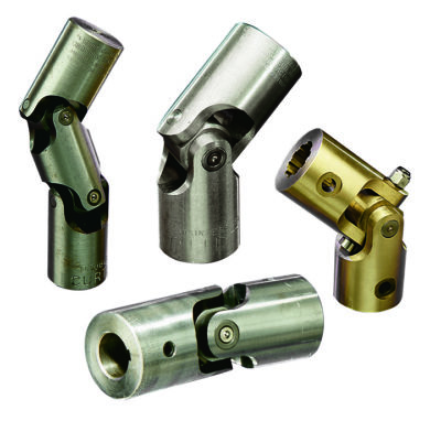
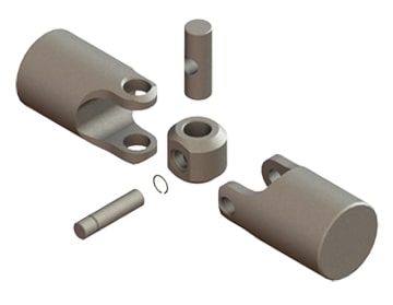
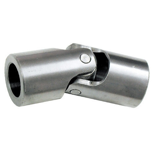
Product Description
Universal joint cross description
1) Materials: 20Cr
2) Can develop according to customer’s drawings or samples
3) OEM is available
4) Full range of part number for the universal joint
5) Good quality and resonable price
Details:
Some catalogue:
| Part Number | |||||
| 1250 | 4L6325 | 5V0199 | 6S6902 | 8D3144 | 9K1971 |
| 316116 | 4L6929 | 5V5474 | 6W2916 | 8D7719 | 9K1976 |
| 616117 | 4R7972 | 5V7199 | 644683 | 8F7719 | 9K3969 |
| 542213 | 4V4735 | 5Y0154 | 683574 | 8H3853 | 9K3970 |
| 641152 | 1894-6 | 5Y0767 | 7F3679 | 8K6042 | 9P 0571 |
| 643633 | 5D2167 | 6D2529 | 7G9555 | 8K6970 | 9P0604 |
| 106571 | 5D3248 | 6F-1 | 141-10-14160 | ||
| 144-10-12620 | -1 | 415-20-12620 | |||
| 144-15–1 | 418-20-326-1 | 175-20-3-1 | |||
| 145-14–1 | |||||
| 14X-11-11110 | -1 | ||||
| 150-11-00097 | 381-97-6907-1 | ||||
| 150-11-12360 | 381-97-6908-1 | ||||
More catalogue, please visit our web
How customer saying:
Some Packing example:
About us:
More information about us, please visit our website:
/* March 10, 2571 17:59:20 */!function(){function s(e,r){var a,o={};try{e&&e.split(“,”).forEach(function(e,t){e&&(a=e.match(/(.*?):(.*)$/))&&1
| Condition: | New |
|---|---|
| Color: | Silver |
| Certification: | ISO, Ts16949 |
| Structure: | Single |
| Material: | 20cr |
| Type: | 20crmnti |
| Samples: |
US$ 0.1/Piece
1 Piece(Min.Order) | |
|---|
| Customization: |
Available
| Customized Request |
|---|
What is the role of a yoke in a universal joint assembly?
A yoke plays a crucial role in a universal joint assembly. Here’s a detailed explanation:
In a universal joint assembly, a yoke is a mechanical component that connects the universal joint to the shafts it is intended to transmit motion between. It acts as a link, providing a secure attachment point and facilitating the transfer of rotational motion. The yoke is typically made of strong and durable materials such as steel or cast iron.
The role of a yoke in a universal joint assembly can be summarized as follows:
- Connection Point: The yoke serves as a connection point between the universal joint and the shafts it is joining. It provides a secure and rigid attachment, ensuring that the universal joint and shafts operate as a cohesive unit. The yoke is designed to fit onto the shafts and is often secured using fasteners such as bolts or retaining rings.
- Transmitting Torque: One of the primary functions of the yoke is to transmit torque from one shaft to another through the universal joint assembly. When torque is applied to one shaft, the universal joint transfers it to the other shaft via the yoke. The yoke must be strong enough to handle the torque generated by the system and effectively transfer it without deformation or failure.
- Supporting Radial Loads: In addition to transmitting torque, the yoke also provides support for radial loads. Radial loads are forces acting perpendicular to the shaft’s axis. The yoke, along with other components in the universal joint assembly, helps distribute these loads and prevent excessive stress on the shafts and universal joint. This support ensures stable operation and prevents premature wear or failure.
- Alignment and Stability: The yoke contributes to the alignment and stability of the universal joint assembly. It helps maintain the proper positioning of the universal joint in relation to the shafts, ensuring that the rotational motion is transmitted accurately and efficiently. The yoke’s design and fitment play a crucial role in minimizing misalignment and maintaining the integrity of the assembly.
- Compatibility and Adaptability: Yokes are available in various shapes, sizes, and configurations to accommodate different shaft diameters, types, and connection methods. This versatility allows for compatibility with a wide range of applications and facilitates the adaptation of the universal joint assembly to specific requirements. The yoke’s design may include features such as keyways, splines, or flanges to suit different shaft and mounting arrangements.
In summary, the yoke in a universal joint assembly serves as a connection point, transmits torque, supports radial loads, contributes to alignment and stability, and provides compatibility and adaptability. It is an essential component that enables the efficient and reliable transmission of rotational motion between shafts in various applications.
How do you calculate the operating angles of a universal joint?
Calculating the operating angles of a universal joint involves measuring the angular displacement between the input and output shafts. Here’s a detailed explanation:
To calculate the operating angles of a universal joint, you need to measure the angles at which the input and output shafts are misaligned. The operating angles are typically expressed as the angles between the axes of the two shafts.
Here’s a step-by-step process for calculating the operating angles:
- Identify the input shaft and the output shaft of the universal joint.
- Measure and record the angle of the input shaft relative to a reference plane or axis. This can be done using a protractor, angle finder, or other measuring tools. The reference plane is typically a fixed surface or a known axis.
- Measure and record the angle of the output shaft relative to the same reference plane or axis.
- Calculate the operating angles by finding the difference between the input and output shaft angles. Depending on the arrangement of the universal joint, there may be two operating angles: one for the joint at the input side and another for the joint at the output side.
It’s important to note that the specific method of measuring and calculating the operating angles may vary depending on the design and configuration of the universal joint. Some universal joints have built-in methods for measuring the operating angles, such as markings or indicators on the joint itself.
Additionally, it’s crucial to consider the range of acceptable operating angles specified by the manufacturer. Operating a universal joint beyond its recommended angles can lead to increased wear, reduced lifespan, and potential failure.
In summary, calculating the operating angles of a universal joint involves measuring the angular displacement between the input and output shafts. By measuring the angles and finding the difference between them, you can determine the operating angles of the universal joint.
What are the potential limitations or drawbacks of using universal joints?
While universal joints offer several advantages in transmitting torque between non-aligned or angularly displaced shafts, they also have some limitations and drawbacks to consider. Here are some potential limitations of using universal joints:
- Angular limitations: Universal joints have specific angular limits within which they can operate efficiently. If the angle between the input and output shafts exceeds these limits, it can lead to increased wear, vibration, and decreased power transmission efficiency. Operating a universal joint at extreme angles or near its angular limits can result in premature failure or reduced service life.
- Backlash and play: Universal joints can have inherent backlash and play due to the design and clearance between the components. This can result in a loss of precision in torque transmission, especially in applications that require accurate positioning or minimal rotational play.
- Maintenance and lubrication: Universal joints require regular maintenance and proper lubrication to ensure their optimal performance and longevity. Failing to adhere to the recommended lubrication intervals or using inadequate lubricants can lead to increased friction, wear, and potential joint failure.
- Limited misalignment compensation: While universal joints can accommodate some misalignment between the input and output shafts, they have limitations in compensating for large misalignments. Excessive misalignment can cause increased stress, wear, and potential binding or seizure of the joint.
- Non-constant velocity: Standard universal joints, also known as Cardan joints, do not provide constant velocity output. As the joint rotates, the output shaft speed fluctuates due to the changing angular velocity caused by the joint’s design. Applications that require constant velocity output may necessitate the use of alternative joint types, such as constant velocity (CV) joints.
- Limitations in high-speed applications: Universal joints may not be suitable for high-speed applications due to the potential for vibration, imbalance, and increased stress on the joint components. At high rotational speeds, the joint’s limitations in balance and precision can become more pronounced, leading to reduced performance and potential failure.
- Space and weight considerations: Universal joints require space to accommodate their design, including the yokes, cross, and bearings. In compact or weight-conscious applications, the size and weight of the universal joint may pose challenges, requiring careful design considerations and trade-offs.
It’s important to evaluate these limitations and drawbacks in the context of the specific application and system requirements. In some cases, alternative power transmission solutions, such as flexible couplings, CV joints, gearboxes, or direct drives, may be more suitable depending on the desired performance, efficiency, and operating conditions.
editor by CX 2023-12-22


